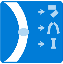
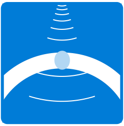
SAWL (3RB) MANUFACTURING PROCESS
Manufacturing and Inspection of Large-Diameter Pipes
Becoming and remaining a market leader requires special abilities. One of the key aspects that sets Berg Pipe apart is our flexibility to deliver pipes in nearly all dimensions and in every quantity. Being a market leader also means providing substantial manufacturing capacities and complementary production technologies. Borusan Berg Pipe Panama City has specialized and optimized the Three Roll Bending (3RB) manufacturing process.
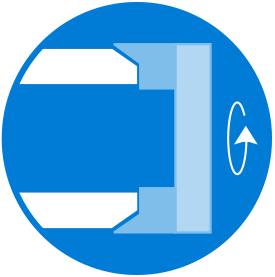
Plate heat and serial numbers are entered into the pipe tracking system. The system checks to make sure the plate is for the order being run and also assigns a unique pipe number to that plate.
The edges of the plate are first milled parallel in the shape of a double Y bevel. Perfectly parallel and square edges as well as close width tolerances are essential for the forming operation. In addition, this is where the accuracy of the weld bevel and the quality of the seam are predetermined. a. During the milling process the pipe number assigned at the Plate Infeed is transferred to the ID of the pipe as well as a scanable bar code with the unique pipe number.
Plate are feed horizontally into the Three-Roll bending machine. The process is controlled with precise hydraulic pressure and positioning of the rolls.
After the plate is rolled into an open can the longitudinal edges of the can need to be further formed so that finished product is are round as possible. This is accomplished with the crimping machine. Different tools are used to form the edges of the plate based on pipe OD, wall thickness and steel grade.
During the crimping process the Pipe number assigned at the Plate Infeed is also transferred to the OD of the pipe. Traceability of the pipe and plate is paramount to ensuring a quality product and that is why some much care is take to ensure accurate tracking of the pipe.
During this process a CNC controlled machine closes the open pipe can. After closing the pipe an automated MIG welding process welds the seam of the pipe. During the welding process a laser seam tracking camera controls the torch position and seam alignment.
Run-on/Run-off tabs are welded to the ends of the pipe. The purpose of the tabs is to provide a place to start and stop the submerged arc welding process. This is done to ensure the submerged arc weld in the pipe is smooth, stable and defect free.
After installing the Run-on/Run-off tabs the operators inspect the automated tack weld and make any repairs if necessary. This is done to avoid the possibility of a blow-through during the Submerged Arc Welding process.
Inside welding is carried out first, followed by outside welding. During the Inside welding process four welding wires are arranged one behind the other at precise spacing and angles. Granular flux is used to shield the wires during welding to avoid atmospheric contamination of the weld.
Consistency of weld quality is determined by various parameters: Welding wire and flux, amperage, voltage, welding speed, wire spacing, wire diameter, the angle of the wires relative to one another and to the weld groove, as well as flux height and width. A welding data monitoring system permits online supervision of the production process. The OD process is carried out much like the ID welding process the difference being 4 or 5 wires are used. The number of wires used is based on pipe wall thickness.
After the pipes are welded the Run-on/Run-off tabs are removed from the pipe. A visual inspection of the entire weld seam both ID and OD is performed. The inspectors are looking for any visual blemishes in the weld seam. (undercuts, porosity, etc.)
Milling robots are used to remove the weld cap on the ID and OD of the pipe. The reinforcement is removed based on customer requirements for field fit-up and welding.
Utilizing Phased Array and fixed angle transducers, each seam is checked for 100% of the weld zone. The Automatic UT inspection can also be augmented by X-ray examination and manual ultrasonic testing.
Digital imaging is accomplished with either a Linear Diode Array detector or computed radiography from a Care Stream system. In either case the digital image is available immediately allowing for quick analysis and disposition of the pipe.
A mechanical expander is used to achieve the final pipe shape. The expansion is performed over the entire length of the pipe. Through this process any camber is removed from the pipe a uniform circumference and ovality is achieved the entire length of the pipe.
In parallel with the nondestructive tests carried out in the large-diameter pipe mills, the mechanical properties of the base metal and weld are measured in accordance with agreed customer specifications.
The ends of the pipes are beveled per the customer specification for field welding or per Berg Pipes internal specification for Girth welded pipes. In either case a double ended beveling machine utilizes specialized carbide inserts and tooling to cut the bevel onto the pipe end.
Pipes have to pass yet another demanding test while still in the mill: by means of internal water pressure, they are stressed close to their theoretical yield point – in other words, far above the operating pressures they will face in service. Once the pipes have passed the hydrotest they are subjected to the final non-destructive testing inspection prior to final inspection and stenciling.
The final Weld Seam UT system is a modern computer-controlled and fully automated machine. It utilizes phased array technology on all channels with the exception of the lamination channels. The machine was designed with the capability of meeting the most stringent industry specifications throughout our entire wall thickness range.
The pipe body UT system utilized ultrasonic wheel transducers to inspect the base metal. The system checks for laminar defects as well as any cracks or seams in the steel. The system is 100% automatic once the operator loads the pipe into the machine. After inspection a detailed map of the pipe surface is generated showing any defects as well as the average pipe wall thickness map.
Digital imaging is accomplished with either a Linear Diode Array detector in the main pipe flow, or computed radiography from a Care Stream system in the alternate pipe flow. In either case the digital image is available immediately allowing for quick analysis and disposition of the pipe.
The final inspection includes additional checks of the OD and ID of the pipe. The pipe diameter, wall thickness, bevels, roundness, etc. are measured and recorded on the pipe body and ends.
After the pipe has passed and been accepted at all previous stations in the mill it can then be stenciled per the customer requirements. The automated stencil station places a stencil inside the pipe end. The information in the stencil includes length, weight, grade all required customer information, the API logo as required as well as a bar code that can be used for further pipe tracking/processing.
Once all production and inspection steps have been carried out and all specification requirements have been fulfilled, the customer documentation is prepared. All results are listed, and certificates are produced.
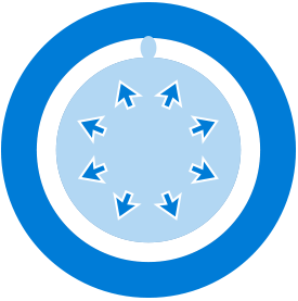
Double-Jointing (Girth-Welding Process)
Double Random Length (DRL) pipes are fed into the Double Jointing process. Pipe bevels are cleaned with a wire brush, then the pipe ends are preheated for welding.
DRL pipes are loading into the station where an internal clamp is used to lineup the two pipe ends. After the operator is satisfied with the lineup a single wire Submerged Arc Weld (SAW) is made on the outside of the pipe joint in the 12 o’clock position while the pipes rotate together.
Depending on wall thickness of the pipes a second SAW process is performed on the joint to fill the balance of the OD bevel joint.
The final SAW process is performed on the ID of the joint. This is accomplished with a boom that carries the welding torch and flux system inside the pipe. In this process the pipe is again rotated while the weld is performed in the 6 o’clock position.
the welded Joint is transferred longitudinally over the X-ray tube boom and into a lead shielded area. A tape is installed next to the girth-weld with lead numbers to identify the joint number & position of the weld. The tape also has Image Quality Indicators (IQI’s) attached to the tape. After the tape is installed the X-Ray tube is powered up. The X-Ray tube and Digital imaging device are aligned and the two devices rotate together around the pipe joint to create a 360 degree view of the girth weld. After X-Ray NDT is complete a visual inspector further evaluated the weld before it leaves the Double Joint facility.