SAWH MANUFACTURING PROCESS
Manufacture and Inspection of Large-Diameter Pipes
Becoming and remaining a market leader requires special abilities. For instance, it requires the flexibility to deliver pipes in nearly all dimensions, in every quantity, and to almost anywhere on Earth. Being a market leader also means providing substantial manufacturing capacities and complementary state of the art production technologies. Borusan Berg Pipe Mobile has specialized and optimized the two-step Submerged-Arc Helical Welding (SAWH) manufacturing process.
Coils are processed at a preparation stand where the lead end is cut square to remove any irregular shape. Coil identity is verified and measurements are recorded to verify material is within required tolerances. Coils are then loaded into the decoiling stand to feed into the mill.
New coils are joined to the previous coil by submerged arc welding to provide a continuous strip.
The skelp is tested for laminar imperfections along both edges and across the full width of the strip using a series of normal beam ultrasonic probes.
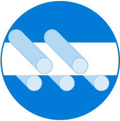
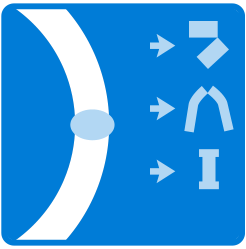
The strip is pushed through a three-roll bending stand and formed into a spiral, with the two edges of the strip meeting after the forming process. The required pipe diameter is obtained by adjusting the feed angle based on the width of the strip, and the orientation of the three roll bending sets to form the ideal radius. The edges of the strip are tack welded together using a continuous single wire gas metal arc welder. Fine tuning of the pipe diameter and strip edge offsets are continually monitored and controlled.
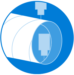
The continuous pipe is then cut into individual pieces to the specified length up to 80 ft. The cut is made without stopping the forming process by a travelling carriage clamped to the moving pipe and an oxygen plasma torch moved around the periphery of the pipe on a rotating frame.
The inside of the pipe is cleaned of loose mill scale and tack welding slag by a rotating brush and vacuum system.
The full-length tack weld is visually inspected to ensure it is properly prepared for submerged arc welding. In order to promote a sound weld along the entire pipe, run-on and run-off tabs are welded on to the pipe ends. This allows any defects caused by instability in the start or stop of the welding process to be cut off with the tabs and discarded.
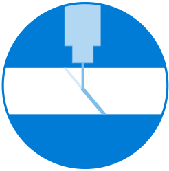
Pipe is welded on one of three welding stands using a three-wire inside pass followed by a two-wire outside pass. The deposits overlap to provide a full penetration weld. The welding process is computer controlled and weld alignment is automatically adjusted by a laser tracking system. The weld wires are submerged in a layer of granular flux which provides shielding to weld puddle from the ambient air and allows impurities to float out of the weld before it solidifies. Unused loose flux is recycled into the system, while hard fused flux is separated and discarded.
The run-on and run-off tabs are removed and the pipe is cleaned using a vacuum system to remove any residual material from the welding process.
Each pipe is measured for dimensional conformance to the specifications and each weld is visually inspected before the pipe is allowed to continue through the production line.
Defects identified during testing and inspection are removed, and the weld is repaired and re-tested and inspected to ensure complete removal of the defect.
The mill computer system indicates any required testing and pipe rings for mechanical testing samples are secured. The mechanical properties of the base metal and the weld are measured in accordance with agreed specifications.
To ensure that the pipe can easily be girth welded in the field, the inside and outside weld caps on each end are ground flush with the pipe body.
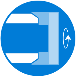
Each pipe end is machined with a bevel for field welding according API 5L standards or customer specifications.
Each pipe is filled with water, sealed and pressurized according to the time and pressure requirements of the relevant specification. A pressure versus time graph is generated for each test cycle and computer archived with the pipe number.
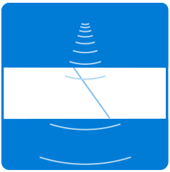
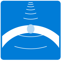
The automated ultrasonic testing station inspects each pipe utilizing a computerized system with up to 12 shear wave probes looking for both longitudinal and transverse defects. Probe alignment is automatically adjusted by a laser tracking system. A test map recording all indications for each test is generated and computer archived. All indications that exceed the alarm level are recorded in the mill computer system and sent to manual ultrasonic testing for final disposition.
Manual ultrasonic testing is performed on each indication exceeding alarm level at the automated ultrasonic testing station. The mill computer system requires that disposition of each individual indication is completed before a pipe can be accepted. In addition, the complete circumference of each pipe end is tested for laminar discontinuities using a straight beam probe.
Each pipe end is tested for a minimum of 8 inches of weld length using computed radiography. In addition, any defects detected by ultrasonic inspection are inspected to provide additional information for repairs and to aid in process changes to improve weld quality.
All required dimensional properties of the pipe are checked for conformance with the specification. Routine measurements are recorded in the mill computer system, verified against process limits, and utilized for data analysis. The pipe is visually examined full-length over the entire inside and outside surface, as well as both ends. Once the pipe passes visual and dimensional requirements, the data is entered into the mill computer system. The system verifies that passing tests have also been recorded for hydrotest, ultrasonic testing of the weld and pipe ends, and radiographic testing before the pipe can be accepted as a prime pipe.
Once all production and inspection steps have been carried out and all specification requirements have been fulfilled, the customer documentation is prepared. All results are listed, and certificates are produced.


